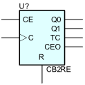
2-Bit Cascadable Binary Counter with Clock Enable and Synchronous Reset
CB2RE is a 2-stage, 2-bit, synchronous, resettable, cascadable binary counter. The synchronous reset (R) is the highest priority input. When R is High, all other inputs are ignored and data (Q1 – Q0) and terminal count (TC) outputs go to logic level zero, independent of clock transitions. The outputs (Q1 – Q0) increment when the clock enable input (CE) is High during the Low-to-High clock (C) transition. The counter ignores clock transitions when CE is Low. The TC output is High when both Q outputs are High.
Larger counters are created by connecting the count enable out (CEO) output of the first stage to the CE input of the next stage and connecting the C and R inputs in parallel. CEO is active (High) when TC and CE are High. The maximum length of the counter is determined by the accumulated CE-to-TC propagation delays versus the clock period. The clock period must be greater than n(tCE-TC), where “n” is the number of stages and “tCE-TC” is the CE-to-TC propagation delay of each stage.
When cascading counters, use the CEO output if the counter uses the CE input; use the TC output if it does not.
Parameters
| Parameter | Description | Units | Default |
|---|---|---|---|
| DELAY | Propagation delay. | s | DGTDELAY |
| IN_MODE | Inputs mode. | IN | |
| OUT_MODE | Outputs mode. | OUT | |
| IOMODEL | The name of an I/O model, which describes the device’s loading and driving characteristics. | DGTDEFIOMODEL | |
| POWER_NODE | Digital power node name. Is the node used by the interface subcircuits which connect analog nodes to digital nodes. | $G_DPWR | |
| GROUND_NODE | Digital ground node name. Is the node used by the interface subcircuits which connect analog nodes to digital nodes. | $G_DGND |