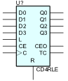
4-Bit Loadable Cascadable BCD Counter with Clock Enable and Synchronous Reset
CD4RLE is a 4-stage, 4-bit, synchronous, loadable, resettable, binarycoded- decimal (BCD) counter. The synchronous reset input (R) is the highest priority input. When R is High, all other inputs are ignored and the data (Q3 – Q0) and terminal count (TC) outputs go to logic level zero on the Low-to-High clock transitions. The data on the D3 – D0 inputs is loaded into the counter when the load enable input (L) is High during the Low-to-High clock (C) transition. The outputs (Q3 – Q0) increment when the clock enable input (CE) is High during the Low-to-High clock transition. The counter ignores clock transitions when CE is Low. The TC output is High when Q3 and Q0 are High and Q2 and Q1 are Low.
Larger counters are created by connecting the count enable out (CEO) output of the first stage to the CE input of the next stage and connecting the R, L, and C inputs in parallel. CEO is active (High) when TC and CE are High. The maximum length of the counter is determined by the accumulated CE-to-TC propagation delays versus the clock period. The clock period must be greater than n(tCE-TC), where “n” is the number of stages and “tCE-TC” is the CE-to-TC propagation delay of each stage.
When cascading counters, use the CEO output if the counter uses the CE input; use the TC output if it does not.
Parameters
| Parameter | Description | Units | Default |
|---|---|---|---|
| DELAY | Propagation delay. | s | DGTDELAY |
| IN_MODE | Inputs mode. | IN | |
| OUT_MODE | Outputs mode. | OUT | |
| IOMODEL | The name of an I/O model, which describes the device’s loading and driving characteristics. | DGTDEFIOMODEL | |
| POWER_NODE | Digital power node name. Is the node used by the interface subcircuits which connect analog nodes to digital nodes. | $G_DPWR | |
| GROUND_NODE | Digital ground node name. Is the node used by the interface subcircuits which connect analog nodes to digital nodes. | $G_DGND |