The keyboard can be simulated in analogue or digital mode. In analog mode, each key has a resistor that varies its resistance according to the position of the corresponding selector. The switch is not quite ideal, in that the resistance can not change from 0 to infinity, but must always have a finite positive value. By proper selection of the RESON and RESOFF resistances, they can be effectively zero and infinity in comparison to other circuit elements.
In digital DROUT mode, the rows correspond to the outputs while the columns are treated as inputs. In digital DCOUT mode, columns correspond to outputs while rows are treated as inputs.
During interactive simulation, the position of the switches can be changed by clicking on them with the mouse.
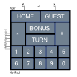
The HOME and GUEST buttons are backlit with an LED. The LED model can be set using the parameters HOMELEDMODEL and GUESTLEDMODEL.
Table of correspondence of the buttons
| Key | Name | Position |
|---|---|---|
| HOME | K1 | R1C1 |
| GUEST | K2 | R1C2 |
| - | K3 | R1C3 |
| + | K4 | R1C4 |
| BONUS | K5 | R2C1 |
| TURN | K6 | R2C2 |
| 1 | K7 | R2C3 |
| 2 | K8 | R2C4 |
| 3 | K9 | R3C1 |
| 4 | K10 | R3C2 |
| 5 | K11 | R3C3 |
| 6 | K12 | R3C4 |
| 7 | K13 | R4C1 |
| 8 | K14 | R4C2 |
| 9 | K15 | R4C3 |
| 0 | K16 | R4C4 |
Parameters
| Parameter | Description | Units | Default |
|---|---|---|---|
| SWMODE | Switch mode. Select from: ANALOG, DROUT, DCOUT. | ANALOG | |
| RESON | On resistance. Used in analog mode only. | Ohms | 10mΩ |
| RESOFF | Off resistance. Used in analog mode only. | Ohms | 1GΩ |
| TSWITCH | Switching time. Within the specified time, the resistance value varies continuously between the current value and the new value. Must be greater than zero. Used in analog mode only. | s | 1ms |
| IN_MODE | Inputs mode. Used in digital mode only. | IN | |
| OUT_MODE | Outputs mode. Used in digital mode only. | OUT | |
| IOMODEL | The name of an I/O model, which describes the device’s loading and driving characteristics. Used in digital mode only. | DGTDEFIOMODEL | |
| POWER_NODE | Digital power node name. Is the node used by the interface subcircuits which connect analog nodes to digital nodes. Used in digital mode only. | $G_DPWR | |
| GROUND_NODE | Digital ground node name. Is the node used by the interface subcircuits which connect analog nodes to digital nodes. Used in digital mode only. | $G_DGND | |
| HOMELEDMODEL | Model to be used for the HOME button LED. See LED Model for information about model parameters. | BLUE | |
| GUESTLEDMODEL | Model to be used for the GUEST button LED. See LED Model for information about model parameters. | ORANGE | |