For some families of components it is possible to create footprints automatically by specifying
the dimensional parameters of the components in the Footprint Wizard dialog box.
The automatic footprint generation procedure creates all the footprint objects within the perimeter of the corresponding frame object
and saves the dimensional parameters of the component in the FWIZDATA attribute of the frame object.
 Tip: Tip: |
|---|
The Footprint Wizard dialog can be activated by selecting the Library » Footprint Wizard » Build Footprint command. |
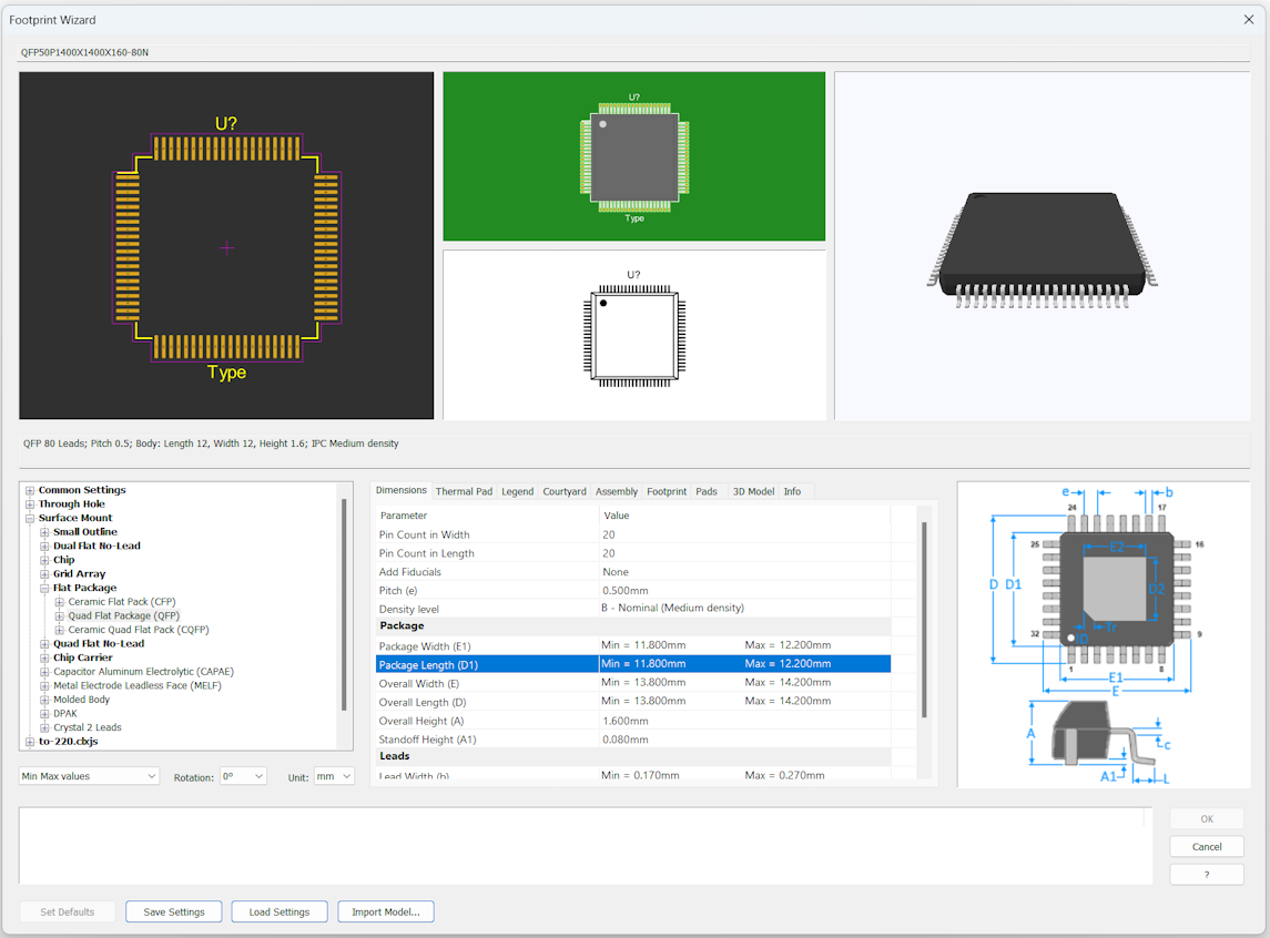
Select the type of component
Expand the Devices group and select the component family in the box on the left. In the box on the right you will see the tabs with the dimensional parameters of the component and the various options.
Input mode
In the Input mode box you can select how you want to enter data about the size of the components. Generally, manufacturers of electronic components specify the dimensions of the components, indicating the minimum and maximum values.
Rotation
In the Rotation box you can set the orientation that the component takes on in the tapes and feed tubes of the Pick & Place machines for PCB assembly. This defines the orientation of the component when it is rotated by zero degrees.
Enter the data
The box on the right shows the tabs in which to enter the dimensional parameters of the component and the various options.
- Dimensions
-
In this tab you must specify the component size, pin number and IPC level of the footprint.
- Thermal Pad
-
In this tab you must specify the size of the thermal pad. Activate the Add Thermal Pad option to add the thermal pad parameters. The Thermal Pad Corners field specifies the percentage of rounding or beveling of the pad corners. The shape of the pad must be specified by a format string in the Thermal Pad Shape field. If no format string is specified, the corners are rounded. The format string can contain up to 4 characters, each of which describes the shape of a corner starting from the one at the bottom right and continuing counterclockwise. For example, the 'BB' format string generates a pad with the right corners beveled and the left corners rounded. You can generate pads with complex shapes by specifying the coordinates of the vertices of the polygon. For more information see the description of the Shaped and User shapes in Pad Style.
- Silkscreen
-
This tab includes some options for drawing the component shape.
- Courtyard
-
This tab includes some options for drawing the component courtyard.
- Assembly
-
In this tab you can set the options and colors to create the component image.
- Footprint
-
In this tab you can choose whether to create the footprint automatically based on the parameters specified for the component size or whether to use the pad size values and distances between pads specified in this tab.
- Pad Style
-
In this tab you can directly set the style of the pads instead of using the dimensions calculated according to the size of the component.
- 3D Model
-
In this tab you can set options for the 3D model.
- Package info
-
Specify some information about the package:
Reference prefix: Specify the prefix of the reference to be used for the component.
Description prefix: Specify the type of component.
Name in library: Specify the name to assign to the frame that defines the footprint. The suffix corresponding to the IPC level of the footprint is automatically added to the name.
Standard name: You can specify the reference standard if available.
IPC name prefix: If available, you can specify the IPC name for the component.
Manufacturer: Specify the name of the manufacturer.
Manufacturer package name: Specify the name assigned by the manufacturer.
Manufacturer package description: Specify the description of the package.
Manufacturer package outline link: Specify the URL of the package specification file.
Manufacturer package weight: Specify the weight of the component in grams.
Settings
Expand the Settings group to specify the default settings.
Creating Footprint Scripts
Using the script language, new footprint models can be easily created. See Creating Footprint Scripts. To import scripts with new model definitions click on the Import Model button.