Single and Multiple Transparent Data Latches
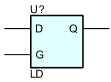
The data output (Q) of the latch reflects the data (D) input while the gate enable (G) input is High. The data on the D input during the High-to-Low gate transition is stored in the latch. The data on the Q output remains unchanged as long as G remains Low.
Parameters
| Parameter | Description | Units | Default |
|---|---|---|---|
| IC | Output initial state. | LOW | |
| DTPLH | Delay from data to out high. | s | DGTDELAY |
| DTPHL | Delay from data to out low. | s | DGTDELAY |
| LETPLH | Delay from enable to out high. | s | DGTDELAY |
| LETPHL | Delay from enable to out low. | s | DGTDELAY |
| IN_MODE | Inputs mode. | IN | |
| OUT_MODE | Outputs mode. | OUT | |
| IOMODEL | The name of an I/O model, which describes the device’s loading and driving characteristics. | DGTDEFIOMODEL | |
| POWER_NODE | Digital power node name. Is the node used by the interface subcircuits which connect analog nodes to digital nodes. | $G_DPWR | |
| GROUND_NODE | Digital ground node name. Is the node used by the interface subcircuits which connect analog nodes to digital nodes. | $G_DGND |