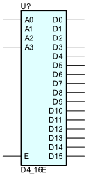
4- to 16-Line Decoder/Demultiplexer with Enable
When the enable (EN) input of the D4_16E decoder/demultiplexer is High, one of 16 active-High outputs (D15 – D0) is selected with a 4-bit binary address (A3 – A0) input. The non-selected outputs are Low. Also, when the EN input is Low, all outputs are Low. In demultiplexer applications, the EN input is the data input. Refer to “D3_8E” for truth table derivation.
Parameters
| Parameter | Description | Units | Default |
|---|---|---|---|
| DELAY | Propagation delay. | s | DGTDELAY |
| IN_MODE | Inputs mode. | IN | |
| OUT_MODE | Outputs mode. | OUT | |
| IOMODEL | The name of an I/O model, which describes the device’s loading and driving characteristics. | DGTDEFIOMODEL | |
| POWER_NODE | Digital power node name. Is the node used by the interface subcircuits which connect analog nodes to digital nodes. | $G_DPWR | |
| GROUND_NODE | Digital ground node name. Is the node used by the interface subcircuits which connect analog nodes to digital nodes. | $G_DGND |