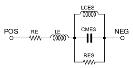
The loudspeaker model consists of two main components: the voice coil DC resistance (RE) and the voice coil inductance (LE).
The electrical equivalents of the major mechanical components of suspension compliance, cone mass and suspension losses, may also be specified (LCES, CMES and RES).

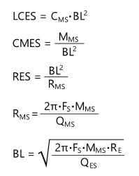
All model parameters can be calculated from the Thiele-Small parameters published by the manufacturer.

- LCES - Depends upon the suspension compliance. The resulting inductance is in henries.
- CMES - Depends upon the cone mass. The resulting capacitance is in farads.
- RES - Depends upon the suspension losses. The resulting resistance is in ohms.
- RMS - The mechanical resistance of a driver's suspension in N·s/m.
- BL - The product of magnet field strength in the voice coil gap and the length of wire in the magnetic field, in tesla-metres (T·m) or (Wb/m).
- CMS - Compliance of the driver's suspension, in metres per newton (m/N).
- MMS - Mass of the diaphragm/coil, including acoustic load, in kilograms.
- FS - Resonance frequency, measured in hertz.
- QMS - Mechanical Q factor at Fs.
- RE - DC resistance of the voice coil, measured in ohms.
- QES - Electrical Q factor at Fs.
External model
As an alternative to using the internal model, it is also possible to use an external model by specifying the name of the subcircuit in the MODEL parameter. The subcircuit must have the following interface:
 Syntax: Syntax: |
|---|
|
.SUBCKT <subcktname> P N ... .ENDS <subcktname> |
Animation
During interactive simulation, you can animate the speaker symbol by specifying values for one of the following three parameter groups:
- WMIN,WRAT,WMAX
- IMIN,IRAT,IMAX
- VMIN,VRAT,VMAX
The above parameters have no electrical function, they are only used for animation of the speaker symbol during interactive simulation.
Parameters
| Parameter | Description | Units | Default |
|---|---|---|---|
| RE | Voice coil DC resistance. | Ohms | 8 |
| LE | Voice coil inductance. If equal to zero, the inductance is not used. | Henries | 0 |
| LCES | Suspension compliance. If this parameter is zero, the LCES component is not used. | Henries | 0 |
| CMES | Cone mass. If this parameter is zero, the CMES component is not used. | Farads | 0 |
| RES | Suspension losses electrical resistance. If this parameter is zero, the RES component is not used. | Ohms | 0 |
| MODEL | Specify the name of the subcircuit. If this parameter is not specified, the internal model consisting of RE, LE, LCES, CMES and RES is used. | ||
| WMIN | Minimum power required to display the animation. | W | |
| WRAT | Nominal speaker power. From minimum power to rated power, a growing wave is displayed. | W | |
| WMAX | Maximum speaker power. A still image is displayed beyond the maximum power. | W | |
| IMIN | Minimum current required to view the animation. | A | |
| IRAT | Rated current in the speaker. From minimum current to rated current, a growing wave is displayed. | A | |
| IMAX | Maximum current in the speaker. A still image is displayed beyond the maximum current. | A | |
| VMIN | Minimum voltage required on the speaker terminals to display the animation. | V | |
| VRAT | Rated voltage at speaker terminals. From minimum voltage to rated voltage, a growing wave is displayed. | V | |
| VMAX | Maximum voltage at speaker terminals. A still image is displayed beyond the maximum voltage. | V | |
Examples
- Speaker Fullrange 15W 8Ω
-
RE=6.8, LE=0.2m, WMIN=0.1, WRAT=15, WMAX=30
- Loudspeaker 35W 8Ω
-
RE=5.8, LE=0.51m, CMES=464.9µ, LCES=6.1m, RES=64.5, WMIN=1, WRAT=35, WMAX=50
- Loudspeaker 75W 8Ω
-
MODEL=G12T75, WMIN=1, WRAT=75, WMAX=100
.SUBCKT G12T75 P N
R_RL P 2 7.5
R_RD1 2 3 15
L_LD1 3 2 20mH
C_CD1 2 3 190u
R_RD2 3 4 0.5
C_CD2 3 4 50u
L_LD2 4 3 100uH
L_LD3 N 4 100uH
R_RD3 N 4 20
.ENDS G12T75
- Electro Mechanical Buzzer with internal drive circuit 12VDC
-
RE=522, VMIN=7, VRAT=12, VMAX=16
- Electro Mechanical Buzzer 5V ac
-
RE=88, IMIN=26m, IRAT=40m, IMAX=64m