All the characteristic parameters of a component are displayed in its properties window where you can edit them accurately.
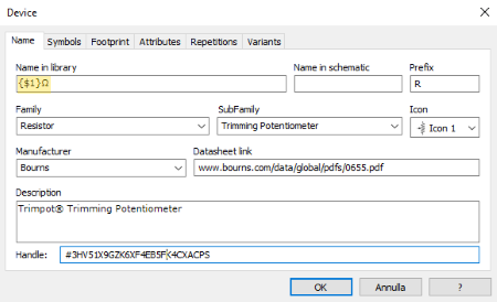
Name
The name of the component and details of the manufacturer and type of component shall be specified on this sheet.
Name in the library
Specify the name to be displayed in the libraries. This name is only used within the library and can be a full name and more descriptive than the one that is inserted in the schema.
Name in schematic
Specify the component name when it is inserted in the schematic. This name is entered in the value field of the symbol when you place it in the schematic. If this field is blank, the component is assigned the same name specified in the Name in the library field. If you specify only the @ character, the symbol retains the name as specified in the symbol definition.
Prefix
Specify the reference name. For example, R for resistors, J for connectors.
Family
Specify the type of component.
SubFamily
Specify the type of component.
Icon
You can specify the icon to associate to the component. There are 32 icons that can be set in the Job Properties dialog box in the group Library.
Manufacturer
In this box you can enter the name of the component manufacturer.
Datasheet link
In this box you can enter a reference to the technical documentation of the component. This field corresponds to the internal attribute ObjDoc. You can specify an internet address or the name of a file. For format see To add documentation to symbols.
Insert the datasheets into a component library
In some cases it may be convenient to insert the component datasheets into the same library in which the components are defined.
Right-click on the name of the project or folder in which the file is to be inserted. The command menu opens.
-
In the menu choose the command Import file. The dialog box in which to select the file to be imported opens.
Select the file and click on Open. The file is stored in the Job.
In the field Datasheet link enter the name of the attached file.
 Tip: Tip: |
|---|
The documentation page can be displayed by selecting the Show datasheet command in the menu that is obtained by right-clicking when the symbol is selected in the graphics editor. |
Description
In this box you can enter a short description of the component.
Handle
This field is read-only and shows the handle of the component tab.
Symbols
In this tab you must specify the name of the symbol to be associated with the component. It is possible to associate more than one symbol to the component but the number and type of pin must be the same for all symbols. To add a new symbol click on the button Add to open the dialog Symbol Builder
Footprint
This box must specify the names of the available footprint for the component. To add a new footprint click the Add button to open the Footprint Builder dialog.
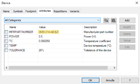
Attributes
This tab lists all the internal attributes associated with the component. Internal attributes are characterized by a name and a value and can be used to associate information to objects. For example: the internal code, price, etc. See Dialog box: Attributes.
 Note: Note: |
|---|
The attributes specified in the component are added to those specified in the symbol and replace the value of attributes that have the same name. |
Repetitions
This section allows you to define a group of similar components using a single component card.
There are 10 variables available (from {$1} to {$10}). The values that characterize the individual components can be assigned to these variables. For example: the value and the part number assigned by the manufacturer.
Variable names can be used in the parameters of the component tab as a placeholder in which to insert the value. For example, in the following image, nine rows are defined and in each row a value has been specified for the variables {$1} and {$2}.
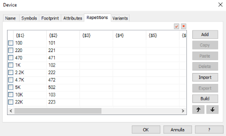
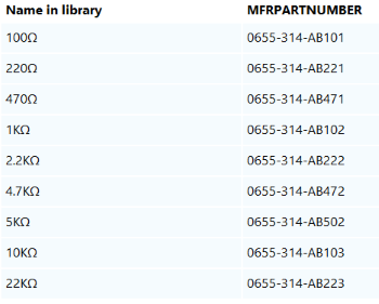
The variable {$1} is used to specify the component name.
The variable {$2} is used to specify the part number assigned by the constructor.
Nine components are created with the following values:
Select the rows
To select a line, activate the check mark at the beginning of the line.
To select all lines, click on the button  ,
to deselect all lines click on the button
,
to deselect all lines click on the button  .
.
Copy the data
You can copy the data to the Windows clipboard and then paste it into other component cards. Only the selected lines are copied.
Exporting and Importing Data
If the same set of values is to be repeated on different component tabs, it may be convenient to export the data to a text file and then import it into the other component tabs. Only the selected rows are exported. In the lines of text, the tab character is used as a data separator.
Variants
In this tab you can specify the components that constitute a variant of this component. For each variant it is necessary to specify the name of the component or the handle of the component card in which it is defined. The description is optional, if entered it is displayed together with the name of the component. The handle is shown in the tab containing the component name and consists of 26 alphanumeric characters prefixed by the # character.