This command allows you to create a keepout area by drawing it as a polyline. In addition to simple linear segments, you can also include arcs and curves.
Example of how to draw a keepout area
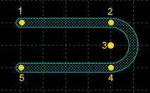
To draw the keepout area shown above:
-
Select the layer on which to draw the keepout area. Keepout objects can be created on the Keepout layer or on any copper layer. Objects placed on the Keepout layer create keepout areas on all copper layers.
-
Choose the PCB » Board » keepout » Polyline command or click the
 tool in the toolbar.
-
Activate the tool menu with the secondary mouse button and choose the command Set width. In the dialog box specify the thickness of the polyline and click on Ok.
-
Position the pointer and click on point (1) to start drawing the shape.
-
Complete the first segment by specifying its end point (2). You can use the pointing device or you can open the dialog box for entering values. In the dialog box, the coordinates of the endpoint can be specified as follows:
By typing the point coordinates directly.
By specifying the offset from the starting point.
Specifying the inclination of the line relative to the horizontal axis and its length.
-
Activate the tool menu with the secondary mouse button and choose the Tool » Arc: Start, Center, End Angle command.
-
Move the mouse over point (3) and click to specify the center of the arc.
-
Activate the tool menu with the secondary mouse button and choose the Toggle direction command or press TAB.
-
Move the mouse over point (4) and click to specify the end point of the arc or press INS and specify an angle of 270°.
-
Activate the tool menu with the secondary mouse button and choose the command Tool » Line.
-
Drag the mouse to draw the next segment and click on point (5).
-
Press ENTER to end the command.
Commands and options
To repeat the command press the SPACEBAR.
To close the tool without drawing the object press ESC.
To remove the last segment press BACKSPACE.
To change the direction of arc, press TAB.
To end the insertion of the points of a spline choose the command Ends the current segment in the tool menu.
Press ENTER to end the command.
To specify the coordinates of the points or the value of the lengths you can use the pointing device or you can press INS to open the dialog box for entering values.