This dialog box allows you to change the properties of each symbol object, the order in which objects are placed within the symbol, and the symbol-specific attributes. The properties of the symbol are listed in five tabs.
Symbol
In questa scheda sono elencate le proprietà del simbolo nello schema elettrico.
Reference
Specifies the reference of the component. For example: R1, U10. The reference is unique for each component of the scheme. If not specified it is the same as the one set in the library, such as R? or U?; The question mark indicates that the reference must be completed during the automatic numbering operation. Further properties related to the reference can be set in the Properties dialog of the Reference object; activate the Objects tab and double-click the Reference object.
Value
Specifies the value of the component or the type. For example: 10K, 74LS00. Further value-related properties can be set in the Value object's properties dialog box; activate the Objects tab and double-click the Value object.
Type
If the component is available in different versions, the available types are listed in this box.
Shape
Lists the available shapes for the object. Multi-shape symbols.
Part
If the component contains multiple parts (e.g. component 74LS00 contains four NAND ports), this box lists the available parts. Select the part number. When you close the dialog box, the component pin numbers are changed according to the selected part number, and a suffix specifying the part number is added to the component reference. The format of the suffix can be set in the Job Properties dialog box; open the Settings group for the schematics and set the value of the Multiple parts format field.
Device ID
During the automatic component annotation operation, the program tries to merge several similar parts into a single physical component giving priority to the symbols with the same Device ID.
Link ID
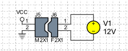
The Link ID is used in the simulation to connect components. For example, a plug with a socket. Components with the same Link ID are connected by matching pins according to their Link ID. In the following example, connectors J5 and J6 have been assigned the same Link ID to indicate that the two components must be connected. To specify the pairing between the pins of the two components, the pin ID of the pins J5-1 and J6-1 was set to 1 while the pins J5-2 and J6-2 were set to 2.
Options
- Show hidden pins
-
Displays any pins that are not visible.
- Keep part number
-
During the automatic component annotation operation, the program tries to merge several similar parts into a single physical component, which may result in a change in the assigned part number. If you do not want the part number to change during a component annotation operation, check this box.
- Exclude from simulation
-
If this box is checked, the symbol will not be inserted in the netlist for simulation.
- Exclude from PCB
-
If this box is checked, the symbol will not be used in the PCB. Enable this option for all virtual component symbols such as simulation-specific SPICE elements.
- Exclude from BOM
-
If this box is checked, the symbol will not be used to generate the bill of materials.
Pin
This tab lists all pins included in the symbol. To view the properties of a pin, double-click the pin name.
Objects
This tab shows the list of all objects included in the symbol. The list shows the stacking order of the objects within the symbol.
To change the properties of objects
Perform the following operations:
Double-click on the object name. The object properties dialog opens.
To change the attributes of objects
Perform the following operations:
Select the object from the list.
-
Choose the command Attributes . The object attributes dialog opens.
To change the stacking order of objects
Perform the following operations:
Select the object to move.
-
Choose the Move up command to bring the object up one position or the Move down command to bring the object down one position.
Footprint
Select the name of the footprint. Click on Add to add a footprint not listed.
Attributes
This tab lists all the internal attributes associated with the symbol. Internal attributes have a name and value and can be used to associate information to objects. For example: internal code, price etc. See Dialog: Attributes.