This command allows you to draw a series of contiguous tracks. Although you can create a series of contiguous tracks, each segment acts as a separate object.
To draw a series of tracks
-
Choose the PCB » Track » Manual routing command or click the
 tool in the toolbar.
-
Specify the starting point.
-
Complete the first segment by specifying its end point. You can use the pointing device or you can open the dialog box for entering values. In the dialog box, the coordinates of the endpoint can be specified as follows:
By typing the point coordinates directly.
By specifying the offset from the starting point.
Specifying the inclination of the line relative to the horizontal axis and its length.
To draw a track at a certain angle, press A and specify the angle.
Specify the endpoints of the other line segments.
To cancel the previous line segment press BACKSPACE.
To insert a Vias and continue on the opposite side press V.
To insert a wire jumper press B.
To insert a printed jumper press J.Press ENTER to end the command or C to end the command including the last segment.
If the track starts on a pad, the routing style set for the class of the connection to which the pad belongs is used, otherwise the current routing style is used.
For the insertion of Vias and Jumpers the layer pairing defined in the dialog PCB Layer Stackup is used.
If the DRC is active and the track you are drawing violates the design rules, an error message appears highlighting the track and/or contact point. See To activate the DRC in the track drawing.
Commands and options
To repeat the command press the SPACEBAR.
To close the tool without drawing the track press ESC.
To cancel the previous line segment press BACKSPACE.
To insert a Vias and continue on the opposite side press V.
To insert a wire jumper press B.
To insert a printed jumper press J.
To specify the coordinates of the points or the value of the lengths you can use the pointing device or you can press INS to open the dialog box for entering values.
-
To change layers click the right mouse button, to open the tool menu, and select the layer in the submenu Change Layer.
-
To change the thickness of the track, click the right mouse button, to open the tool menu, and select one of those available in the submenu Track Width.
-
To change the style of the vias, click the right mouse button, to open the tool menu, and select one of those available in the submenu Via Style.
Drawing mode
When you place a track there are 8 placement Modes. The mode specifies how angles are created when you place tracks and angles to which tracks can be placed. Press the TAB key to scroll through the modes or the ALT key to select the opposite mode to the active one. You can change modes at any time while drawing the track.
 Note: Note: |
|---|
In all modes other than Any angle, the line segment connected to the cursor shows the next segment. The segment you are currently placing precedes this Segment. |
The Looking-Ahead feature
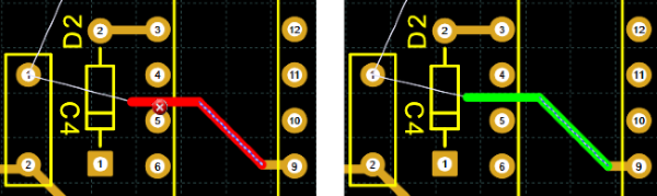
When you draw a track, the segment attached to the cursor represents the next segment. The segment you are currently placing precedes this segment. This function is useful for ending a segment at the exact point where it is to start the next one so that you can easily get around obstacles. In the following example, the segment you are positioning is the one identified by the dashed line. The next segment, i.e. the segment connected to the mouse cursor, shows an incorrect positioning in the left image and the correct positioning in the right image.