The pins define the connection points for the input and output signals from an electrical symbol. The properties of a pin are listed on two tabs.
Type
This tab defines the electrical properties of the pin.
Name, Number and Label
The label assigned to a pin is displayed instead of the pin name when the pin name is set to invisible. Assign a value to the pin label only if the name to be displayed on the symbol is different from the actual name of the pin: for example in IEEE symbols.
Single Pin
Specify the number, name and, if applicable, the label of the pin.
Pin of a Multi-Part Component
Multipart components are those components that contain several equal parts represented by the same symbol. For example, the 74LS00 component is a multi-part component because it contains four two-input NAND ports. For this type of component can be used as a symbol the NAND port where for each pin you must specify, separating them with commas, the numbers and names that the pin assumes for each part.
For example, for component 74LS00:
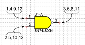
in the Number field you must indicate: (1,4,9,12) for input A, (2,5,10,13) for input B and (3,6,8,11) for output Y
in the Name field you must indicate: (1A,2A,3A,4A) for input A, (1B,2B,3B,4B) for input B and (1Y,2Y,3Y,4Y) for output Y
Pin with bus functionality
A pin with bus functionality represents a group of pins with a single graphic symbol. This type of pin allows you to create simplified symbols in which all pins corresponding to data or address lines are represented with a single pin. To specify that a pin has Bus functionality you must tick the option As Bus.
In the Number field you must specify, separating them with commas, the numbers of all the pins belonging to the bus and in the Name field you must report, in the same order, the names.
For example, for component 27C64:
in field number you must indicate: 11,12,13,15,16,17,18,19
in the name field you must indicate: D0,D1,D2,D3,D4,D5,D6,D7
Multiple pins
A multiple pin represents with a single graphic symbol a group of pins with the same electrical function and the same name. For example, some components have multiple ground line terminals (GND) that are internally short-circuited. To specify a multiple pin, check the Multiple pin option.
In the Number field you have to specify, separating them with commas, the numbers of all the pins and in the Name field you have to specify the name.
Symbols
Symbols added to the pin allow you to show the electrical characteristics of the pin. These symbols are purely graphic. The electrical characteristics of the pin are determined only by the Electrical Type parameter.
- Inside
-
Select the symbol to be added internally to the component's graphic symbol.
- Inside edge
-
Select the symbol to be added on the inside edge of the component graphic symbol.
- Outside edge
-
Select the symbol to add to the outer edge of the component graphic symbol.
- Outside
-
Select the symbol to add outside the component graphic symbol.
Electric type
Select the electrical characteristics of the pin. The electric type is used during the compilation of the electrical schematic and the ERC. Select from the following:
Input: Input pin;
Output: Output pin;
Bidirectional: Input/Output pin;
Passive: Pin of a passive element (resistor, capacitor ecc.);
Three State: Output pin, which can achieve high-impedance;
Open Collector: Open collector pin;
Open Emitter: Open emitter pin;
Power In: Power supply pins of a component (Vcc, Vss, Gnd);
Power Out: Pin giving power as the output pin of 7812 voltage regulator;
Undefined: Pin with function not clearly defined;
Swap ID
Swap ID is used to group equivalent pins together. Equivalent pins are pins that can exchange connections without affecting the functionality of the electrical circuit. For example, the input pins of an AND logic are equivalent to each other. Swap ID is useful when routing a PCB to exchange connections on the pins of a component to simplify track design.
Link ID
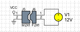
The Link ID is used in the simulation to connect components. For example, a plug with a socket. Components with the same Link ID are connected by matching pins according to their Link ID. In the following example, connectors J5 and J6 have been assigned the same Link ID to indicate that the two components must be connected. To specify the pin assignment of the two components, the Link ID of pins J5-1 and J6-1 has been set to 1 and the Link ID of pins J5-2 and J6-2 has been set to 2.
Net Class
Select the connection class for this pin. The Net classes define the Net styles. They include the wire style in the electrical schematics and the DRC and Routing classes for the PCB. See Net Classes.
Pin number in library
This field displays the number assigned to the pin in the symbol in the library. It is not necessary to fill in this field as it is automatically filled in when the symbol is placed in the drawing. This parameter has the same format as the Number parameter and is used to identify the pin in the simulation models.
The simulation models are connected with the symbol pins using the pin number specified in the library and not the current pin number. In fact, once the symbol is placed in the schematic, the pin number may change depending on the package selected for the component.
Options
- As Bus
-
A pin with bus functionality represents a group of pins with a single graphic symbol. This type of pin allows the creation of simplified symbols in which all the pins corresponding to data or address lines are represented with a single pin.
- Multiple pins
-
A multiple pin represents with a single graphic symbol a group of pins with the same electrical function. For example, some components have multiple ground line terminals (gnd) that are internally short-circuited.
- Hidden pin
-
In some components, such as those belonging to logical families, power supply pins may be hidden. Enabling this option specifies that the pin is hidden. When the netlist is created, all hidden pins are automatically connected to other hidden pins with the same name and to connections with the same name. This option only takes effect if the pin is included in a symbol. Free pins on a symbol definition page are always visible.
- Visible line
-
When this option is enabled, the line connecting the two characteristic points of a pin is visible.
- Number visible
-
Determines whether the pin number is visible.
- Number in vertical
-
Specifies the orientation of the number when the pin is placed vertically.
- Visible name
-
Determines whether the pin name is visible.
- Name in vertical
-
Specifies the orientation of the name when the pin is placed vertically.
- Pin not electrically connected
-
When this option is enabled, it is specified that the pin is not electrically connected and should be ignored during the ERC. An unconnected pin is highlighted by the following symbol
 .
The color and size of the symbol can be set in the document properties dialog box.
.
The color and size of the symbol can be set in the document properties dialog box.
- No ERC
-
When this option is enabled, it is specified that the pin should be ignored during the ERC. An No ERC pin is highlighted by the following symbol
 .
The color and size of the symbol can be set in the document properties dialog box.
.
The color and size of the symbol can be set in the document properties dialog box.
- Skip if hidden
-
The pin is ignored if this option is enabled and the pin is hidden.
- Graphic object only
-
If this option is active, the pin will be created without electrical functionality. A non-electric pin is only a graphic object and must be used when the symbol requires the presence of some pins for representative purposes only.
- Swap number and name positions
-
Allows you to exchange number and name positions.
- Automatic number and name position
-
Indicates whether the name and pin number should be repositioned automatically when the pin is rotated.
- Show only first pin number
-
When this option is enabled for a Multiple or Bus pin, only the first pin number is shown instead of showing all pin numbers.
Style
Select the style from those listed or create a new one.
Graphics
This tab defines the graphic properties of the pin. A pin consists of two points. The first point is the anchor point to the component, while the second point is the electrical terminal.
Anchor point
Specify the coordinates of the point where the pin begins.
- X
-
Specify the horizontal position.
- Y
-
Specify the vertical position.
Plug point
Specify the coordinates of the point where the pin ends. The coordinates of the second endpoint can be specified as follows:
- In absolute coordinates
-
Specify the horizontal position in the X box and the vertical position in the Y box.
- In coordinates relative to the starting point
-
Specify the distance of the end of the line from the start point in the fields Dx and Dy.
- In polar coordinates from the starting point
-
Specify the line length and the angle it forms with respect to the x-axis in the fields Length and Angle.