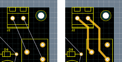
The PCB routing operation replaces the existing logical connections between the components with physical connections made with copper traces. The existing logic connections between the pads of the components are represented by thin lines that extend from the center of a pad to the center of another pad belonging to the same net. The set of all the connection lines constitutes the Ratsnest. In the following image, the existing logical connections between the pads shown on the left, have been replaced by physical connections made through copper tracks.
Choice of view
The view used for routing must make the set of connection lines visible. The connection lines are displayed on the Nets type layer, so the view used for routing must include a Nets type layer. To set the display options of the connection lines, open the Layer Setup and select the Nets layer in the current view.
To view the connection lines of a single net
-
In the PCB Panel, view the connection list by selecting netlist in the upper list box or right-click to open the menu and select netlist.
-
Right-click the Net name to open the command menu.
-
Choose the Ratsnest » Exclusive command.
To view the connection lines of all nets
-
In the PCB Panel, view the connection list by selecting netlist in the upper list box or right-click to open the menu and select netlist.
-
Right-click to open the command menu.
-
Choose the Ratsnest » Show all command.
Setting the project rules
Before starting the routing operations, set the design rules. The DRC classes define the electrical design rules for the PCB. A DRC class is a set of rules that define the distances that must be respected between the different elements present on the PCB, to such as the distance between a pad and a track or the distance between two pads. DRC rules can be assigned to a Net or Layer so that you can define electrical rules that only apply to tracks and the pads of a given Net or present on a given layer. See DRC classes.
 Tip: Tip: |
|---|
The set of rules used for automatic PCB check can be set in the PCB tab in the Project Properties dialog box. The dialog can be activated by selecting the Settings » Project Properties command or by using the key combination CTRL+ALT+P. |
Manual PCB routing
The routing operation consists of creating physical connections between components using tracks, arcs and vias. The display of connection lines and the active DRC in the drawing editor simplify the manual routing operation.
Online DRC
If the DRC is active and the track you are drawing violates the design rules, an error message appears highlighting the track and/or contact point. See To activate the DRC in the track drawing.
To route a net
-
In the PCB Panel, view the connection list by selecting netlist in the upper list box or right-click to open the menu and select netlist.
-
Right-click the Net name to open the command menu.
-
Choose the Manual Routing command. All connection lines that are not connected to the selected net are hidden and the tool for drawing tracks is activated.
Click on a pad belonging to the selected net and draw the first track segment then continue inserting via and other track segments until you reach the next pad. The routing parameters, track width and vias style are set according to the connection class. You can change the routing parameters and layer by selecting commands in the tool menu. See To draw a series of contiguous tracks.
To remove all traces of a net
Do one of the following:
-
-
In the PCB Panel, view the connection list by selecting netlist in the upper list box or right-click to open the menu and select netlist.
-
Right-click the Net name to open the command menu.
-
Choose the Unroute command. All traces and vias belonging to the connection are removed.
-
-
-
Choose the command PCB » Routing » Unroute » Net or click the tool
 in the toolbar.
The Unroute net dialog box opens.
in the toolbar.
The Unroute net dialog box opens.
In the dialog box, select the nets to remove and click OK. All traces and vias belonging to the connection are removed.
-
-
-
Choose the command PCB » Routing » Unroute » Picked or click on the tool
 in the toolbar.
The cursor takes the form of a black arrow.
in the toolbar.
The cursor takes the form of a black arrow.
Click on an object, track, pad or vias of the connection. All traces and vias belonging to the connection are removed.
-
To remove all traces from the PCB
-
Choose the PCB » Routing » Unroute » All command or click on the tool
 in the toolbar.
All traces and vias are removed from the PCB.
in the toolbar.
All traces and vias are removed from the PCB.
To drag a track
-
Open the Snap dialog and enable the Drag tracks when moving components option. If this option is disabled, connectivity is not maintained and the track is simply moved. Alternatively, you can press the CTRL key when you click on the track you want to drag.
-
Select the track and drag it to the new location.
To split a track
-
Select the track segment to be split.
-
Press the right mouse button to open the menu and choose the command Draw track. The segment is deleted and a connection line appears instead.
-
Restore connectivity by inserting track segments and vias.
To select tracks
-
Select a single segment of a track.
-
Press the right mouse button to open the menu and choose the command Select branch to add to the selection all the segments belonging to the same branch of the selected one or the command Select tree to select all the track segments that are part of the same sub-connection.
Automatic PCB routing
Before starting the autorouter, check the correct setting of the design rules.
Setting Layer Routing Options
To set the routing options for the different layers of the PCB, do the following:
-
Open the Layer Setup dialog.
In the Layers box select the layer to set.
In the properties box, expand the Options group and select the Routing tab.
Set the routing options.
Protect existing tracks
If you have already traced some nets by manual routing, and you do not want them to be modified by the autorouter, you need to protect the tracks by setting the Autouter Fixed option in the track properties window. To protect all existing tracks, set the Protect all existing tracks option in the autorouter's Setup dialog box.
To route a single net
Do one of the following:
-
-
In the PCB Panel, view the connection list by selecting netlist in the upper list box or right-click to open the menu and select netlist.
-
Right-click the Net name to open the command menu.
-
Choose the Autorouting command.
-
-
-
Choose the command PCB » Routing » Routing Picked or click on the tool
 in the toolbar.
 -
Click on a pad to route the entire net or click on the wire to route only that part of the net.
-
To route the PCB with the Grid Autorouter
-
Choose the command PCB » Routing » Autorouter or click on the tool
 in the toolbar.
The Autorouter dialog opens.
in the toolbar.
The Autorouter dialog opens.
Select the nets to track and the tool to use.
Click on Ok. The dialog box in which to set the specific options for the selected autorouter opens.
Set the options and start the autorouter by clicking on Ok.
To route the PCB with FreeRouting Autorouter
-
Choose the command PCB » Routing » Autorouter or click on the tool
in the toolbar.
The Autorouter dialog opens.
Select the nets to track and the tool to use.
Click on Ok. The autorouter application starts while waits for the response file.
In the Autorouter application, route the PCB. At the end, choose the command File » Save and Exit.
To route the PCB with ELECTRA Autorouter
-
Choose the command PCB » Routing » Autorouter or click on the tool
in the toolbar.
The Autorouter dialog opens.
Select the nets to track and the tool to use.
Click on Ok. The dialog box in which to set the specific options for the selected autorouter opens.
Set the options and click on OK.
The autorouter application starts while waits for the response file.
In the Autorouter application, route the PCB. At the end, export the file Specctra Session file (.ses).
To route the PCB with an autorouter with SPECCTRA® interface
-
Choose the command PCB » Routing » Autorouter or click on the tool
in the toolbar.
The Autorouter dialog opens.
Select the nets to track and the tool to use.
Click on Ok. The dialog box in which to set the specific options for the selected autorouter opens.
Set the options and click on OK.
A dialog box opens in which you can specify the name of the file in Specctra Design (.dsn) format.
Specify the name of the file and click on Ok. The application of the autorouter is started. The dialog box from which to import the Specctra Session File (.ses) generated by the autorouter opens.
In the Autorouter application, import the Specctra Design file (.dsn) file and route the PCB. At the end, export the file Specctra Session file (.ses).
In , import the file Specctra Session file (. ses) generated by the Autorouter.