It is possible to divide a copper area into electrically distinct sub-areas by simply drawing the boundary line between them. Each sub-area can be assigned a different net and filling style.
To divide a copper area
To divide the plane into two distinct zones as in the image: Select the copper object to be divided and perform the following operations:
-
Choose the command PCB » Copper » Split » Cutter width or click on the tool
 in the toolbar.
A dialog box opens in which you can specify the thickness of the boundary line between the two zones.
in the toolbar.
A dialog box opens in which you can specify the thickness of the boundary line between the two zones.
-
In the dialog box specify the thickness and click on Ok.
-
Choose the command PCB » Copper » Split » Split area or click on the tool
 in the toolbar.
The mouse cursor takes the form of a cross.
in the toolbar.
The mouse cursor takes the form of a cross.
-
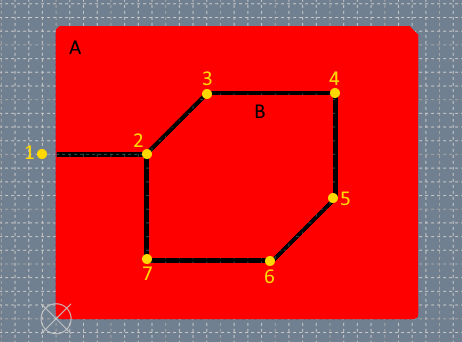
Click on point 1 to start drawing the boundary line. To cut the edge of the copper area it is necessary that the border line crosses the edge.
-
Move the mouse and click later on the points: 2, 3, 4, 5, 6, 7, 2.
-
Press ENTER to end the boundary line between the two zones. The copper area has been divided into external sub-area A and internal sub-area B.
To change a boundary line in a copper area
The boundary line that divides a copper object has the same geometric structure as a shape object and can therefore consist of a sequence of connected line, arc, or curve segments. When a copper object is selected and the Edit tool is active, the control hooks of the individual segments that make up the boundary line and a blue hook in the center of each zone are displayed.
When the control hooks of a boundary line are visible in a copper object, you can perform the following operations:
Drag the hooks located in the vertices of the linear segments.
Drag the hooks on the ends of the arcs to adjust the opening of the arc.
-
Drag the hook placed in the center of an arc to move the arc.
-
Drag the control hooks of a Bezier curve.
-
Drag the control hooks of a spline curve.
Click anywhere on the object and drag the mouse to move the object.
Right-click on a hook to display the corresponding menu of commands.
Commands in the menu of a hook on the border line.
| Command | Description |
|---|---|
Move All |
Moves all active hooks. Displays the Move dialog box. |
Deselect All |
Deactivates all active hooks. |
Select Hook |
Activates the clicked hook. |
Deselect Hook |
Disables the clicked hook. |
Cutter » Delete cutter |
Removes the borderline. |
Cutter » Set clearance |
Opens the dialog box for setting the borderline thickness. |
Cutter » Move Vertex |
Displays the dialog box in which to specify the new vertex coordinates. |
Cutter » Insert Vertex |
Adds a new linear segment by inserting a vertex at the midpoint of the segment. |
Cutter » Remove Segment |
Removes the segment to which the hook belongs. |
Cutter » Convert to Line |
Converts the segment to a line. |
Cutter » Convert to Arc |
Converts the segment to an arc. |
Cutter » Convert to Bezier |
Converts the segment to a Bezier curve. |
Cutter » Convert to Spline |
Converts the segment to a spline curve. |
Cutter » Toggle Direction |
Reverses the direction of the arc. |
Cutter » Set Center |
Set the center of the arc. |
Cutter » Set Axes |
Sets the length of the axes of an ellipse arc. |
Cutter » Start Angle |
Displays the dialog box in which to specify the new value of the starting angle. |
Cutter » End Angle |
Displays the dialog box in which to specify the new value of the end angle. |
Cutter » Move Point |
Displays the dialog box in which to specify the new coordinates of the point of a spline curve. |
Cutter » Insert Point |
Adds a new point in a spline curve. |
Cutter » Remove Point |
Removes a point from a spline curve. |
Cutter » Angular |
Sets the point of a Bezier curve as the angular point. |
Cutter » Smooth |
Sets the point of a Bezier curve as a slight damping point. |
Cutter » Symmetrical |
Sets the point of a Bezier curve as a symmetrical point. |
Move Copper
|
Displays the Move dialog box. |
Rotate Copper
|
Displays the Rotate dialog box. |
Properties Copper
|
Displays the Properties dialog box. |
Show reference point
|
Displays the transformation center of the selection. The transformation center is initially hidden and is set in the center of the selection rectangle. See the Transformation center. |


To change the type of filling and the net of a copper sub-area
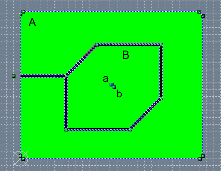
You can set the fill type and net of each sub-area independently. In the previous image, the copper area was divided into two sub-areas A and B. To set the GND net for sub-area A and the VCC net for sub-area B, do the following:
-
Select the Edit tool.
-
Select the copper object. The control hooks are displayed.
-
Right-click on the blue hook (a) in the centre of the sub-area A. In the menu choose the Properties Area command. The dialog box for the properties of sub-area A opens.
-
In the dialog box select the net GND and the fill "PCB Hatch (0.5mm)" then click on Ok.
-
Right-click on the blue hook (b) in the centre of the sub-area B. In the menu choose the Properties Area command. The dialog box for the properties of sub-area B opens.
-
In the dialog box select the VCC net and the "PCB Hatch (45° 0.5mm)" fill and click on Ok.